Floating vs Trunnion Ball Valve: Design, Torque and Selection
Key Takeaway
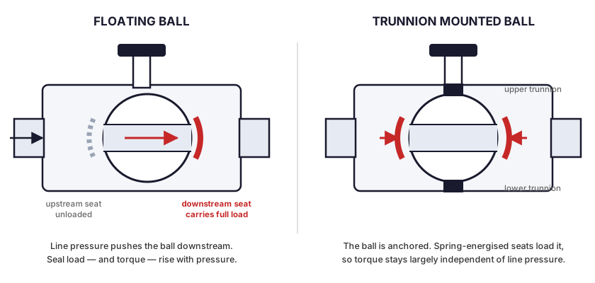
A floating ball valve holds the ball between its two seats. Line pressure pushes the ball downstream and the downstream seat carries the whole thrust, which is what forms the seal. A trunnion mounted valve anchors the ball on upper and lower bearings that absorb the thrust, and seals with spring-loaded seats instead. Everything else follows from that one difference. Floating seat load rises with the square of the bore and in proportion to differential pressure, so torque climbs steeply with both. Trunnion torque stays comparatively flat, and each seat can be made to seal on its own, which is what allows double isolation. No standard sets a size at which one replaces the other. In common practice the change happens between DN150 and DN200 at Class 150 and 300, and at smaller sizes from Class 600 upward.
How does a floating ball valve seal?
A floating ball valve is a quarter-turn valve in which the ball is held only by its two seats and can move a short distance along the flow axis. The stem drives it through a slot in the top of the ball but does not locate it.
Close the valve and differential pressure acts on the upstream face of the ball. The ball shifts downstream until it is pressed into the downstream seat, and that contact stress is the seal.
Sealing force is therefore a property of the service rather than of the valve. Thrust delivered into the downstream seat is approximately:
F ≈ ΔP × π/4 × d² (d = seat bore)
Worked through at the ASME B16.34 Class 150 rating for Group 2.2 materials, 275 psi at 100°F, which is the group covering CF8M. These are calculated from the formula at nominal full-port bore, not manufacturer data:
| Full-port size | Seat bore | Thrust on downstream seat at 275 psi |
|---|---|---|
| DN25 (1") | 25.4 mm | 216 lbf (0.96 kN) |
| DN50 (2") | 50.8 mm | 864 lbf (3.8 kN) |
| DN100 (4") | 101.6 mm | 3,456 lbf (15.4 kN) |
| DN150 (6") | 152.4 mm | 7,776 lbf (34.6 kN) |
The 6 inch valve loads its seat thirty-six times as hard as the 1 inch valve at identical pressure. PTFE and reinforced PTFE have finite compressive strength, so past some combination of size and pressure the seat cold-flows, the ball beds into it, and both torque and seat life fall away.
That is the physical ceiling on the floating design, and it is the reason the crossover exists at all.
What changes when the ball is trunnion mounted?
A trunnion mounted ball valve locates the ball on an upper and a lower trunnion running in bearings carried by the body. The bearings absorb the pressure thrust and the ball does not translate.
Sealing has to come from somewhere else. Trunnion valves carry the seat rings in bores as small pistons, energised by springs and assisted by line pressure acting behind the seat.
Two consequences matter when specifying. Torque is largely decoupled from line pressure, because it now arises from bearing friction and seat spring load rather than from pressure-driven ball-to-seat friction. And each seat can be made to seal independently, which is the mechanical basis for double isolation.
The cost is complexity. Bearings, seat springs, seat inserts, cavity relief provisions and additional concentric machined surfaces are all features that can be specified or manufactured badly.
SPE and DPE seats
Trunnion seats behave in one of two ways, and the difference governs what happens to pressure trapped in the body cavity.
SPE, single piston effect or self-relieving. The seat is energised by line pressure from the pipeline side only. If cavity pressure rises above line pressure, the seat lifts off the ball and vents the cavity back into the line.
DPE, double piston effect. The seat is energised from both sides, so cavity pressure pushes it harder onto the ball. It seals better and it does not relieve.
This maps directly onto the isolation classes in API 6D. DIB-1 uses two DPE seats, so a DIB-1 valve normally requires an external cavity relief valve or a drilled body vent. DIB-2 uses one DPE and one SPE seat, and the SPE side provides the relief path.
Where does the crossover sit?
No standard defines it. API 608 and ISO 17292 both cover metal ball valves in either construction, and neither mandates one above a given size. The table below reflects common practice, not a rule.
| Class | Usually floating | Usually trunnion |
|---|---|---|
| Class 150 / 300 | Up to DN150 (6") | DN200 (8") and above |
| Class 600 | Up to DN100 (4") | DN150 (6") and above |
| Class 900 and above | Small bore only | Effectively all sizes |
Treat it as a starting point and check it against the duty. A DN100 valve at Class 300 held at full differential pressure for months is a harder application than a DN150 valve at Class 150 stroked once a year. Operating frequency, media temperature and time spent closed under load all move the line.
A floating valve offered above the usual range is not automatically wrong. Some designs use PEEK or metal-backed seats specifically to extend it. Ask for the seat material, the differential pressure the design was validated at, and the torque figure at that pressure.
How should torque be specified?
Operating torque has three contributors. Ball-to-seat friction dominates, and in a floating valve it is proportional to differential pressure, because differential pressure is what generates the seal load. Stem seal friction is roughly constant, though it rises as packing is retightened over the life of the valve. Bearing friction is the trunnion valve's main contributor and is comparatively insensitive to pressure.
A quoted maximum torque with no stated pressure is not usable data.
Ask instead for break torque and running torque at the design differential pressure, at both temperature extremes of the service. For actuator selection a safety factor over the stated valve torque is normal practice, and valves that sit closed under load for long periods warrant a larger one, because seat relaxation and adhesion raise break-away torque above the catalogue figure. Ask the actuator supplier what factor their sizing assumes, since it is not a fixed convention. ISO 5211 defines the mounting interface and says nothing about torque, so the two are specified separately.
Seat material sets the ceiling
Because seat load rises with the square of the bore, seat material decides whether a floating design is viable at a given size and pressure. Typical continuous service limits, which vary by manufacturer and compound:
| Seat material | Typical upper limit | Behaviour under high seat load |
|---|---|---|
| Virgin PTFE | 200°C (392°F) | Excellent sealing, lowest strength, cold-flows under sustained load |
| RPTFE, glass or carbon filled | 230°C (446°F) | Better creep resistance; the usual choice as size or pressure climbs |
| PEEK | 250–260°C (482–500°F) | High strength, extends the floating range, raises torque, less forgiving of surface finish |
| Metal seated | Above 300°C (572°F) | Highest load capacity, requires lapping, accepts a higher leakage class |
What DBB and DIB actually mean
Both terms come from API 6D, and both are used loosely in quotations and in specifications.
DBB, double block and bleed. One valve that in the closed position blocks flow from both ends and provides a means of venting the cavity between the seats. A two-seat floating valve with a body cavity vent can satisfy this.
DIB, double isolation and bleed. Each seat individually seals against pressure in the body cavity. That requires seats able to hold pressure from the cavity side, which a floating design does not have.
The failure mode is a specification that says double block and bleed when the intent was double isolation. Write DBB, DIB-1 or DIB-2 explicitly and the ambiguity disappears.
Two stem features both standards require
API 608 and ISO 17292 require both of the following. Neither is visible on a finished valve, so both are worth naming in the purchase specification.
- Blowout-proof stem. The stem is inserted from inside the body and retained by a shoulder, so line pressure cannot eject it if the gland nut is removed while the valve is pressurised.
- Antistatic device. A spring or pin maintaining electrical continuity between ball, stem and body, so that charge generated by flow cannot accumulate on an isolated ball. Required for flammable service and inexpensive to include.
How do you verify what was quoted?
A quotation that repeats the specification back is a claim. Three parts of it can be checked independently.
Material
A material test report to EN 10204 3.1 certifies a heat of steel. It does not certify that the casting in front of you came from that heat. Positive material identification with a portable spectrometer on the finished body closes that gap, and the substitution it catches is the one with a commercial motive behind it. CF8M contains molybdenum and CF8 does not, and a body swapped to the cheaper alloy passes visual inspection indefinitely.
Ask separately whether the supplier melts its own castings or buys them. With an in-house foundry the material record begins at the melt, inside the same quality system that ships the valve. With bought-in castings it begins at a third party's gate. Both arrangements work. They differ in how far a problem can be traced without a second company's cooperation.
Testing
API 598 defines the shell and seat test, and any supplier will confirm they run it. The procedure is not where suppliers differ. Capacity is. Ask how many test positions the plant has relative to its assembly lines, and what the rigs are rated to as distinct from the pressure your valve is tested at. Equipment headroom is what allows an elevated customer test to run inline rather than being subcontracted.
Calibration
Spectrometry, hardness, dimensional and pressure data all rest on it. Ask for the calibration register and which accredited body the standards trace to. It is one line in an RFQ and it separates a documented quality system from a decorated one.
Side by side
| Characteristic | Floating ball | Trunnion mounted ball |
|---|---|---|
| Ball restraint | Held by seats only, moves axially | Anchored by upper and lower trunnions |
| Carries pressure thrust | Downstream seat | Trunnion bearings |
| Source of seal load | Line pressure on the ball | Spring-energised seats with pressure assist |
| Torque against pressure | Rises with differential pressure | Comparatively flat |
| Torque against size | Rises steeply, seat load ∝ d² | Rises moderately |
| Sealing at very low pressure | Depends on seat preload | Springs maintain contact |
| Double isolation (DIB) | Not available | Available, DIB-1 or DIB-2 |
| Part count and repair complexity | Low | Higher |
| Usual economic range | To DN150 at Class 150–300 | DN200 upward, or high class |
Frequently Asked Questions
The short version:
Seat load, not size, decides the construction. Work out the thrust at your real differential pressure before assuming a size rule applies, and ask for torque at that pressure rather than a catalogue maximum. If the specification involves isolating a cavity, write DBB, DIB-1 or DIB-2 explicitly and state whether cavity relief is required, because DIB-1 normally needs an external relief provision. Below the crossover the floating design is the simpler machine and usually the right one.
Related Articles
- API 598 Is Three Tests, and Only One Is About Shut-Off
- OEM Ball Valve Manufacturer: Range, Capacity and Certifications
- Industrial Ball Valve Guide: Types, Selection & Applications
- 2-Piece vs 3-Piece Ball Valve: Design Differences & When to Use Each
- Full Port vs Reduced Port Ball Valve: Performance & Cost Comparison
- Ball Valve Pressure Ratings Explained: ASME Class 150 to 600
- Ball Valve Seat Material Guide: PTFE vs RPTFE vs PEEK vs Metal
- Ball Valve Actuator Types: How to Choose the Right One
- Is CF8M the Same as 316? What Changes When a Ball Valve Body Is Cast
Referenced standards: ASME B16.34 (pressure-temperature ratings), API 608 (metal ball valves, flanged, threaded and welding end), ISO 17292 (metal ball valves for petroleum, petrochemical and allied industries), API 6D (pipeline and piping valves, source of the DBB, DIB-1 and DIB-2 definitions), API 598 (valve inspection and testing), API 607 and API 6FA (fire type-testing), ISO 5211 (part-turn actuator attachment), EN 10204 (types of inspection documents). Publisher pages: ASME, API.
275 psi at 100°F is the ASME B16.34 Class 150 rating for Group 2.2 materials, which include CF8M. Group 2.1, covering CF8, is rated 285 psi at the same temperature. Seat thrust figures are calculated from the stated formula at full-port nominal bore and are indicative; actual seat bore varies by manufacturer. Seat temperature limits are typical published ranges and are not a substitute for a specific manufacturer's pressure-temperature chart. The size and class bands given for the floating to trunnion crossover describe common practice and are not defined by any standard.