Why Is Liquid Cooling Turning Manual Ball Valves Into Actuated Ones?
Key Takeaway
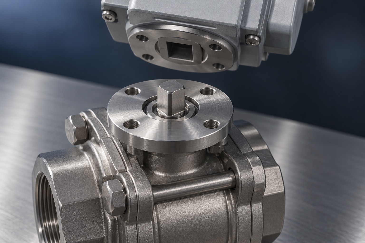
Liquid cooling does not simply add valves. It moves them out of the plant room and into the rack row, where four conditions make a lever impractical: no operator is present in the aisle, a coolant leak beside energised electronics has to be isolated in seconds, redundant paths have to be switched on command, and fill and flush sequences run to a schedule. Each condition converts a valve that would have carried a handle into a valve that carries an actuator and a signal wire. That conversion changes the body, not just the top. An actuated valve needs an integral ISO 5211 pad rather than a bracket, a stem sized for actuator torque and side load, a seat that survives thousands of cycles instead of dozens, and live-loaded packing. A body specified for manual duty will pass its shell test and still fail in service, because the failure shows up as stem leakage and rising breakaway torque after a few thousand cycles, which no factory acceptance test looks for.
Where the New Valves Actually Come From
In an air-cooled hall the water stops at the CRAH coil. Isolation valves live in the chilled water plant and in the riser. A technician reaches them on foot, and their population is set by the number of air handlers.
Direct-to-chip cooling breaks that arrangement in two. A coolant distribution unit sits between the facility water system and a separate technology cooling system, and the secondary side carries treated fluid out to manifolds, down each rack, and into cold plates sitting on the processors. Every one of those branch points is a place where a technician must eventually be able to shut off flow without draining the row.
The count follows from topology rather than from any published ratio. A CDU needs isolation on both sides of both loops. A manifold pair needs isolation at the top and the bottom. A rack branch needs isolation if a single rack is ever to be serviced while its neighbours keep running. Published per-rack valve counts vary widely between designs, and a rear-door heat exchanger retrofit produces a different figure again, so the honest statement is that valve population scales with the number of independently serviceable branches, and liquid cooling multiplies those branches.
Why Those Particular Valves Cannot Stay Manual
Four constraints apply on the secondary side, and each one on its own is enough to rule out a lever.
| Condition on the secondary side | Why a lever fails | What the valve needs instead |
|---|---|---|
| No operator in the aisle | The cost of operating the valve is the trip to it, not the valve | Remote command over the building network |
| Leak beside energised hardware | An alarm that ends in a phone call responds in minutes | Actuator wired to leak detection, with a defined fail position |
| N+1 CDU changeover | Redundancy becomes only as fast as the staffing | Actuator with position feedback to confirm the path |
| Fill, flush and commissioning | A valve outside the controls has to be worked around | Actuator on the control network, in the sequence |
No operator is present in the aisle
A valve inside hot aisle containment is behind a door, in a restricted area, at a height that may need a platform. The cost of operating it is not the valve, it is the trip.
Leak response is measured in seconds
Coolant in a direct-to-chip loop runs within the rack envelope, above and beside energised hardware. Leak detection cable or a tray sensor can raise an alarm quickly, but an alarm that ends in a phone call has a response time measured in minutes. An actuator wired to the same alarm closes on the signal.
Redundant paths have to be switched, not walked to
Where CDUs are deployed N+1, one unit can be taken out of service without dropping the load it was carrying. The changeover is a valve operation. If it is manual, the redundancy is only as fast as the staffing.
Fill, flush and commissioning run to a sequence
A secondary loop is filled, vented, flushed and proven before it carries load, and the same sequence repeats after a component is replaced. Sequences of that kind are written into the controls, and a valve that is not in the controls has to be worked around.
What Changes in the Valve Body
This is the part that gets specified last and causes the most trouble. Bolting an actuator onto a valve designed for hand operation changes the duty in four measurable ways.
| Property | Manual isolation valve | Actuated valve on a cooling loop |
|---|---|---|
| Operations over service life | Tens to a few hundred | Thousands, set by the control sequence rather than by people |
| Actuator interface | Lever and stop plate | ISO 5211 pad, sized F03 to F07 in the small line sizes |
| Stem loading | Hand torque, applied in line | Actuator output torque plus the side load of a cantilevered mass |
| Seat duty | Static sealing, occasional movement | Repeated wear track, creep under sustained load |
| Stem seal | Single packing set, adjusted by hand if it weeps | Live-loaded, so spring washers hold gland compression as the packing creeps |
| Failure that ends its life | Seat leakage | Stem leakage and rising breakaway torque |
The mounting pad decides whether the valve is genuinely actuator-ready
ISO 5211 defines the attachment between a part-turn actuator and a valve: a bolt circle, a pilot diameter and a drive that is square or double-D. The flange sizes used on small line sizes are F03 at a 36 mm bolt circle, F04 at 42 mm, F05 at 50 mm and F07 at 70 mm, with F10 at 102 mm and F12 at 125 mm above them.
| ISO 5211 flange | Bolt circle diameter |
|---|---|
| F03 | 36 mm |
| F04 | 42 mm |
| F05 | 50 mm |
| F07 | 70 mm |
| F10 | 102 mm |
| F12 | 125 mm |
The full table, F03 to F100 with the spigot recess, the bolt thread and the flange heights, together with the hole positions and the designation letters, is in the ISO 5211 reference.
The bolt circle figures are the ISO 5211 values. Confirm the flange size and the drive dimension against the valve drawing before ordering an actuator.
A valve can meet that dimensionally in two ways. The pad can be cast and machined as part of the body or the bonnet, or it can be a bracket bolted on with a coupling to the stem. The bracket version is cheaper and it is what a catalogue often means by actuator-ready.
The difference shows up in lost motion. A bracket adds a joint and a coupling between the actuator output and the ball, and any clearance in that chain becomes angular play. The actuator reports ninety degrees of travel while the ball travels slightly less, and the stop position shifts with the direction of the previous stroke, so the seat contact band moves instead of repeating. It also transfers the actuator mass through the bracket into the stem as a bending load rather than into the body.
Seat material stops being a temperature decision
On a manual valve the seat is selected against media and temperature. Under cycling it is also selected against creep and wear.
Virgin PTFE deforms under sustained compressive load, so a valve that has stood closed takes a compression set against the ball and its breakaway torque rises above the value measured on a recently cycled valve. Filled grades reduce that. RPTFE with 15 or 25 percent glass raises compressive strength and wear resistance at the cost of some conformability, and PEEK raises both a great deal further, asking for more torque in return. Glycol content in a secondary loop pushes the decision as well, because the mixture raises viscosity and changes the wetting behaviour at the seat face.
| Seat material | Creep under sustained load | Operating torque | Where it fits on a cooling loop |
|---|---|---|---|
| Virgin PTFE | Highest of the four | Lowest | Low operation counts, clean water, manual duty |
| RPTFE, 15% glass | Reduced | Moderate | General actuated duty, the usual first step up |
| RPTFE, 25% glass | Lower again | Higher | Higher seat load or higher cycle counts |
| PEEK | Lowest of the four | Highest | High cycle counts where the actuator has torque headroom |
Cycle count is a specification, and there are standards that measure it
Valve standards mostly test pressure containment, not endurance. ASME B16.34 sets pressure-temperature ratings, API 598 and ISO 5208 define shell and seat testing, and none of them tells you what the valve does after five thousand operations.
The standards that do measure cycling come from fugitive emission testing. ISO 15848-1 defines endurance classes for isolating valves at 205, 1 500 and 2 500 mechanical cycles, tested with a measured leakage limit at the stem. API 641 type tests quarter-turn valves over 610 mechanical cycles with stem emissions held below 100 ppmv. Neither standard was written for cooling water, and neither is a cooling qualification. They are useful because they are the only widely recognised way to state a cycle count with a stem leakage limit attached, which is exactly the pair of numbers an actuated cooling valve is judged on.
| Standard | What it measures | What it does not tell you |
|---|---|---|
| ASME B16.34 | Pressure-temperature ratings by material and class | Anything about cycle life |
| API 598 | Shell, backseat and seat leakage at manufacture | Anything about cycle life |
| ISO 5208 | Seat leakage rate classes A to D | Anything about cycle life |
| ISO 5211 | Actuator attachment dimensions and drive form | Torque, endurance or whether the pad is integral |
| ISO 15848-1 | Stem leakage over endurance classes at 205, 1 500 and 2 500 cycles | Behaviour in water or glycol; the test fluid is helium or methane |
| API 641 | Stem emissions below 100 ppmv over 610 mechanical cycles | Behaviour in water or glycol; the test fluid is methane |
The Sizing Error Worth Correcting
Actuator sizing is commonly done by taking the seated torque from the valve catalogue and applying a safety factor. The figure in the catalogue is normally a clean, ambient, water-service number taken on a valve that has just been cycled.
The condition that decides whether the actuator is big enough is different. It is breakaway torque on a valve that has stood in one position at loop temperature, in a glycol mixture, for weeks. The seat has taken a compression set against the ball, and the torque needed to move it the first few degrees is higher than the catalogue value. An actuator chosen on the clean number and a modest factor can stall on a valve that has done nothing wrong.
Ask for the breakaway figure after a dwell period at temperature, in the actual fluid, and size against that. If a supplier can only give the ambient number, that is worth knowing before the order rather than after commissioning.
What Belongs on the Enquiry
An enquiry that carries these items can be quoted against. One that does not will be quoted as a manual valve with a pad on top.
- Line size, pressure class and the fluid, including glycol type and concentration
- Loop temperature range, and the temperature the valve sits at when it is not moving
- Expected operations per year, and whether the valve holds one position for long periods
- ISO 5211 flange size required, and whether the pad must be integral to the body
- Stem drive form, square or double-D, and the dimension across flats
- Breakaway torque after dwell at temperature, not only seated torque at ambient
- Stem leakage limit, and whether an ISO 15848-1 or API 641 result is required
- Whether the valve must be serviceable in line, which decides two-piece against three-piece
- End connections, and whether the actuator envelope clears the adjacent rack
What This Does Not Settle
Electric and pneumatic actuation are not decided by the arguments above. Both meet all four constraints. The choice between them turns on whether compressed air is available at the rack and on what the valve must do when power or air is lost. It is covered separately in the actuation comparison linked below.
Valve counts per rack are also not settled here. They are a function of how many branches a given design makes independently serviceable, and that varies between direct-to-chip layouts, rear-door retrofits and immersion. A number taken from one reference design does not transfer to another.
Frequently Asked Questions
Related Articles
- API 598 Is Three Tests, and Only One Is About Shut-Off
- Ball Valve Actuator Types: Electric, Pneumatic, Hydraulic and Manual
- Direct-to-Chip vs Rear-Door Valve Requirements
- Ball Valves for Data Center Liquid Cooling
- Ball Valve Seat Material Guide: PTFE vs RPTFE vs PEEK vs Metal
- Why Data Centers Choose Three-Piece Ball Valves
- Three-Piece Sanitary Ball Valve, Clamp or Butt Weld Ends
- Stainless Steel Ball Valve OEM Manufacturing in Taiwan
Referenced standards: ISO 5211 (part-turn actuator attachments), ISO 15848-1 (fugitive emission type testing and endurance classes), API 641 (type testing of quarter-turn valves for fugitive emissions), ASME B16.34 (pressure-temperature ratings), API 598 and ISO 5208 (valve inspection, testing and leakage rates), API 608 and ISO 17292 (metal ball valves, blowout-proof stem requirement).
Liquid cooling loop terminology follows ASHRAE TC 9.9 datacom guidance on facility water and technology cooling systems, and Open Compute Project cooling environments material. Bolt circle dimensions are the nominal ISO 5211 values and are not a substitute for a specific actuator or valve drawing. Seat material behaviour is stated from published polymer property data and is not a service life prediction.