Why Are Data Center Cooling Valves Electric Rather Than Pneumatic?
Key Takeaway
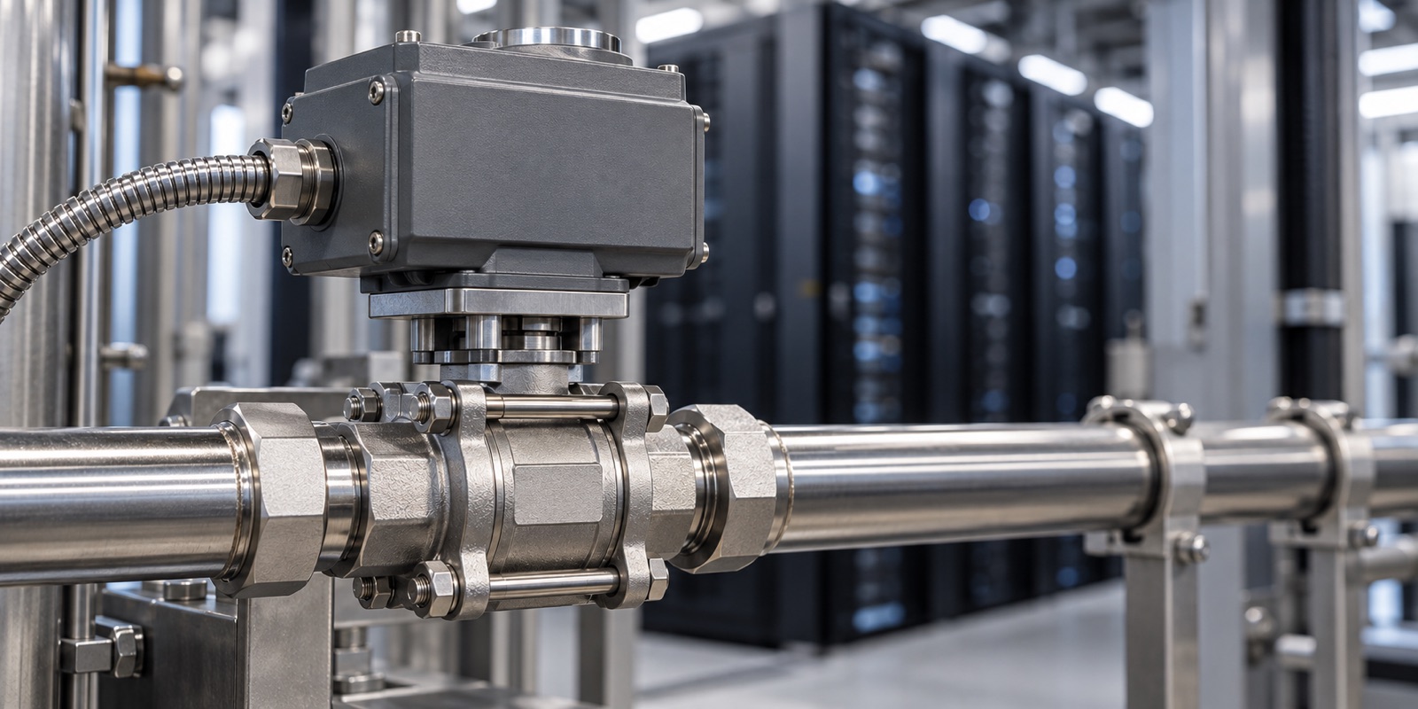
A data hall has no compressed air main. It has power, it has that power on UPS and generator, and it has a control network reaching every rack row. Electric actuation uses three utilities that are already there; pneumatic actuation would need a compressor, a dryer, a receiver and an air line brought into a space designed to keep water and contaminants out. The decision that actually needs engineering attention is not electric against pneumatic. It is what the valve does when the power goes away, and whether the actuator is rated for the number of times a day it will be asked to move.
The utility that settles it
Walk the mechanical plant of a chemical works and you will find an air main running above the pipe rack, because half the instruments and most of the valves need it. Walk a data hall and there is no air main. There is power distribution, there is a network, and there is chilled or warm water in the secondary loop. A compressor room exists in a plant building because many devices need air. In a data hall the actuated valves would be the only load on it, so the whole cost of the air system would sit on them.
That is most of the answer, and it is worth saying plainly rather than dressing it up as a performance comparison. Pneumatic actuation is not worse. It is unavailable.
The rest of the answer is that the three utilities the hall does have happen to be exactly what an electric actuator wants. Power is present at every rack row. That power is already behind a UPS and a generator, so an actuator can be treated as a load that rides through a transfer. And the building management system already speaks to every other device in the hall over Modbus or BACnet, so an actuator that reports position is one more point on a network that exists.
A pneumatic actuator in the same position would need an air supply that is clean and dry to a specified class, a receiver sized for the number of strokes after a compressor trip, and a length of tubing carrying 60 to 125 psi into a room whose entire design intent is to keep fluids away from electronics. Every one of those is solvable. None of them is free, and none of them buys anything the electric unit does not already provide.
What being on the network is actually worth
An isolation valve that only opens and closes could run off a local switch. The reason data center valves sit on the control network is that the cooling loop is not a fixed system. Rack load moves through the day, redundant CDUs swap, and maintenance isolates one branch while the rest keeps running.
Three things follow from that.
Position feedback. Knowing that a valve was commanded shut is not the same as knowing it is shut. An actuator with position feedback tells the BMS which of those two is true, and that distinction is what lets an operator isolate a branch from a console instead of sending someone into a hot aisle with a torch.
Modulation. A modulating actuator holds the valve at an intermediate position, so flow follows a temperature signal instead of being switched on and off. In a warm-water loop that is the difference between running the plant at design flow all day and running it at what the racks actually need.
Temperature class matters here. ASHRAE TC 9.9 classifies facility water supply by its maximum temperature: W17, W27, W32, W40, W45 and W+, where the number is the maximum supply temperature in degrees Celsius. A W17 loop and a W45 loop are different problems. The higher classes let a site reject heat with dry coolers for much of the year, and they also sit close enough to the limits of a virgin PTFE seat that the seat choice stops being automatic. Seat materials covers where those limits fall.
Fail position is the real decision
In a fire damper or a fuel line the safe position is obvious. In a cooling loop it is not, and the reflex answer is wrong often enough to be worth stating.
A valve isolating a rack branch that closes on power loss has just removed cooling from hardware that is still holding heat. If the power event is a transfer that the UPS rides through, the racks are still drawing power and still producing heat while their coolant supply is shut. Fail closed protects the building from a leak and exposes the load to a thermal excursion. Fail open does the reverse.
Which one is right depends on what the valve is for. A branch isolation valve and a bypass valve in the same loop can reasonably take opposite answers. So can a valve upstream of a leak detection zone and one downstream of it.
The point for a specification is that this cannot be left to the actuator supplier's default. Stay-put is what a plain on-off unit does, and it is a legitimate answer. It should be chosen rather than inherited from the actuator's default setting.
The error worth correcting: duty cycle
This is where specifications go wrong in a way that does not show up for months.
Electric actuator motors are rated to IEC 60034 duty classes. An on-off actuator is commonly an S2 motor, short-time duty, built to run for a few minutes and then stop. A modulating actuator needs S4, intermittent periodic duty with starting, and the percentage matters: an S4 25 % rating means the motor may run 2.5 minutes inside a ten-minute window and must rest for the remaining 7.5 to shed heat.
| Duty class | What it means | Where it belongs | What happens if misapplied |
|---|---|---|---|
| S2, short-time duty | Runs for a defined short period from cold, then stops | Isolation valves that move a few times a day | Overheats when asked to modulate |
| S4, intermittent periodic duty with starting | Repeated start-run-rest cycles; the percentage sets run against rest in a ten-minute window | Control valves following a temperature signal | Undersized percentage still overheats, just more slowly |
| Continuous-rated | Runs indefinitely | Valves that hunt constantly around a setpoint | Paying for capacity an isolation valve will never use |
The failure mode this produces is quiet. An on-off actuator put on a modulating loop does not fail on commissioning day. It works, gets warm, works, gets warmer, and then a thermal cut-out opens somewhere in month four with no obvious cause. The valve is fine. The valve body is fine. The motor was rated for fewer starts than the control loop asks of it.
If flow is trimmed to follow rack temperature, the actuator is in modulating service regardless of what the datasheet calls the valve. The word on the line list does not change how many times a day the motor starts.
What the valve body has to carry
An actuator is bolted to a valve that has to have been built for it, and three things on the valve side decide whether the pairing works.
The mounting pad is machined, not added. ISO 5211 defines the flange face, the bolt circle and the designation, F03 through F16 for the sizes that appear in this service. The pad is a machined feature on the top of the body, and moving from one designation to the next changes the bolt circle and usually the stem drive with it. The ISO 5211 dimensions are what the actuator supplier quotes against.
The stem has to transmit the torque. The drive form at the top of the stem, square, double-D or keyed, has to match the actuator bore, and it has to be sized for the torque rather than for the lever that used to be there. Retrofitting an actuator onto a valve supplied with a hand lever generally means a new stem as well as a new top flange.
Breakaway torque sizes the motor, not running torque. A ball valve that has sat closed under pressure needs more torque to start moving than to keep moving, because the seat material has crept into the surface of the ball over the dwell. An electric actuator has no stored-energy reserve to call on for that first moment, so the margin has to be in the motor rating. Why liquid cooling is turning manual valves into actuated ones sets out how that dwell behaviour is measured.
What belongs on the enquiry
An actuated valve is two purchases that have to agree with each other. The valve side is covered in the specification guide. The actuator side adds these.
- Supply voltage, and whether the supply is on UPS, on generator, or on neither
- Control signal: on-off, floating, or analogue, and the protocol if it is networked
- Feedback required: position, torque, fault, or none
- Fail position, stated per valve function rather than per project
- Duty class and percentage, based on the expected number of starts per hour
- Breakaway torque of the valve after the longest expected closed dwell, not the catalogue running torque
- ISO 5211 designation and stem drive form
- Enclosure rating for the location, which in a hall with liquid cooling is not the same as an office ceiling void
What this does not settle
Nothing here covers control valve sizing. A valve chosen to modulate needs a Cv calculation and an authority check against the rest of the circuit, and that is a different exercise from picking an isolation valve. Cv and sizing is the starting point.
Actuator brand selection is outside this as well. The duty class, the fail position and the ISO 5211 designation are properties of the requirement, and every reputable actuator manufacturer publishes them. Compare those figures rather than the marketing around them.
Enclosure ratings, hazardous area classification and functional safety requirements each have their own standards, and a data hall with a leak detection scheme may impose requirements that none of the above anticipates.
Frequently Asked Questions
Related
- Manual, pneumatic or electric: matching the actuator to the duty
- Direct-to-chip and rear-door cooling: valve requirements compared
- Stainless steel ball valve OEM manufacturer in Taiwan — product range, in-house processes and test capacity