Direct-to-Chip vs Rear-Door Cooling: Valve Requirements Compared
Key Takeaway
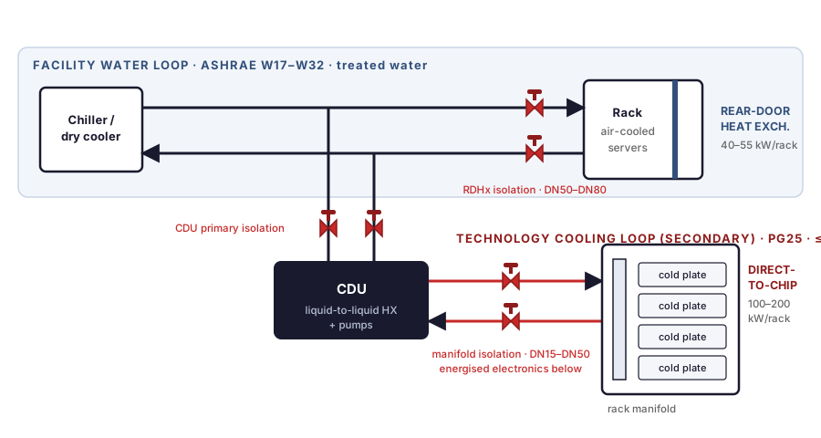
Comparisons of these two architectures usually stop at kilowatts per rack. For anyone writing a valve specification the decisive question is which loop the valve sits in. A rear-door heat exchanger is fed from the facility water loop, so its isolation valves are line-size building-services valves, commonly DN50 to DN80, and a weeping joint reaches the floor. Direct-to-chip cold plates are fed from the CDU secondary loop, so the valves are smaller, commonly DN15 to DN50 at the rack manifold, the fluid is an inhibited glycol mixture, and a weeping joint sits above energised boards. Pressure class rarely constrains either side. Seat and seal material, leak tightness, cleanliness and serviceability do.
What separates the two architectures?
A rear-door heat exchanger replaces the cabinet's rear door with a liquid-to-air coil. Server fans still move the air and the coil catches the heat on the way out. Nothing inside the server changes. Vendor-published capacities are quoted in the tens of kilowatts per rack and rise as the inlet water gets colder.
A direct-to-chip design brings liquid to a cold plate clamped onto the processor or accelerator package, removing heat at source rather than after it has been released into the room. Single-phase direct-to-chip is what makes sustained rack densities of a hundred kilowatts and above practical, generally with N+1 coolant distribution and dual-header rack manifolds.
Many facilities run both: rear doors retrofitted onto legacy rows, direct-to-chip on new ones. That leaves two distinct valve populations, and the useful way to split a consolidated valve list is by loop rather than by rack.
Which loop does the valve sit in?
Data centre liquid cooling is described as two loops separated by a heat exchanger. The facility water system, or primary loop, carries treated water from chillers, dry coolers or cooling towers around the building. The technology cooling system, or secondary loop, is the closed controlled-chemistry loop between the CDU and the IT equipment.
Rear-door heat exchangers are connected to facility water in most designs. Their isolation valves are conventional building-services valves in a conventional building-services environment.
Direct-to-chip manifolds sit on the secondary side, where everything is tighter. The fluid is specified by the CDU vendor, the chemistry is monitored, and the narrowest passage in the whole system is the cold plate channel, on the order of a millimetre or less.
| Rear-door heat exchanger | Direct-to-chip | |
|---|---|---|
| Loop the valve sits in | Facility water, primary | Technology cooling, secondary |
| Typical valve size | DN50–DN80 (2"–3") | DN15–DN50 (½"–2") |
| Fluid | Treated facility water | Inhibited glycol and water, commonly 25% propylene glycol; deionised water in some designs |
| Supply temperature band | Typically ASHRAE W17–W32 | Warmer operation practical, W32–W45 designs in use |
| Loop pressure | Building distribution pressure | Commonly limited to 690 kPa (100 psi); normal operation often at or below 414 kPa (60 psi) |
| Consequence of a weep | Floor, containment, corrosion | Energised boards directly below |
| Cleanliness requirement | Normal pipework practice | Specified; particulate reaches cold plate channels |
| Service access | Rack rear, door open, IT running | Inside the rack, often requires node shutdown |
Does pressure class ever decide the valve?
Secondary loops run at low pressure by the standards of an industrial valve. One published rack-cooling specification caps its secondary loop at 690 kPa (100 psi), with normal operating pressure at the heat exchanger well below that. Against figures of this order, an ASME Class 150 valve in CF8M, rated 275 psi at 100°F under ASME B16.34, carries a large margin. Confirm the numbers against the CDU actually selected, because they are set by the equipment rather than by a standard.
What the pressure class does not address is whether the seat still holds after several hundred cycles, whether the stem seal weeps under thermal cycling, whether the valve can be serviced without cutting pipe, and whether anything inside it will shed particles into the loop.
Why is leak tolerance different on the two sides?
Rear-door piping runs at the back of the cabinet, routed under floor or overhead. A weeping union is a maintenance ticket. Contain it, catch it, fix it at the next window. Nothing is destroyed while the ticket waits.
Direct-to-chip branch piping runs inside the rack, above and alongside powered boards. The same weep rate is a different event, which is why drip trays, leak-detection cabling and dry-break couplings are standard on the secondary side.
It also changes what a good valve looks like there. A three-piece body allows the centre section to be removed for seat replacement without disturbing the pipework or the manifold, which in a dense rack with a short downtime window outweighs a small saving on a two-piece body.
How does the fluid change seat and seal selection?
Facility water and secondary-loop coolant are different problems.
Secondary loops commonly run an inhibited propylene glycol and water mixture, frequently around 25 percent glycol, or treated and deionised water. The inhibitor package, rather than the glycol itself, usually sets the material limits, and inhibitor chemistry varies by CDU vendor. Request the fluid specification and pass it to the valve supplier instead of describing the fluid as glycol and leaving it there.
The mixture is also thermally and hydraulically worse than water in both directions at once. A propylene glycol mixture carries less heat per unit mass than water and is appreciably more viscous at the same temperature. Greater flow is needed for the same duty and that flow costs greater pressure drop, so full-port bodies earn their cost where pump head is constrained.
| Wetted component | Facility water (rear-door) | Secondary loop (direct-to-chip) |
|---|---|---|
| Body and end connections | Bronze, carbon steel or stainless, depending on loop chemistry | SS316 (CF8M); copper alloys generally excluded |
| Ball and stem | Stainless, chrome-plated brass in some building products | SS316 |
| Seat | PTFE or RPTFE | PTFE or RPTFE, selected against the inhibitor package |
| Stem and body seals | PTFE, EPDM common in water service | Selected against the fluid and the full thermal cycle including cold standby |
| Zinc-bearing alloys | Managed by loop treatment | Avoid; dezincification products travel to the cold plate |
On temperature, ASHRAE TC 9.9 renamed its liquid cooling classes in the fifth edition of the Thermal Guidelines to W17, W27, W32, W40, W45 and W+, where the number is the maximum supply fluid temperature in degrees Celsius and every class carries a lower limit of 2°C. Direct-to-chip makes the warmer classes viable, because heat is captured at source at a temperature high enough to reject without mechanical cooling for much of the year. For valve selection this reaches the stem seal, which on a loop cycling between cold standby and W45 operation sees a wide temperature excursion and the differential expansion between PTFE packing and stainless stem that comes with it.
Cleanliness and leak tightness are decided by process
These two requirements appear in secondary-loop specifications often and are verified rarely, because neither is visible on a finished valve.
Cleanliness is a manufacturing step
A machined stainless valve leaves the lathe carrying cutting fluid, fine swarf in the thread roots and the seat pocket, and handling residue. None of it is visible at arm's length. All of it becomes mobile once the valve is filled with warm glycol and pumped, and its destination is the cold plate channel.
The answer is a cleaning stage designed into the route between machining and assembly, with ultrasonic cleaning as the usual method, followed by controlled assembly and capped packaging so the valve arrives as it left. That is a process decision taken long before any individual order, which is why it belongs in the RFQ rather than in a receiving inspection. When auditing for it, the question is not whether the supplier cleans valves but where in the routing the step sits, what the method is, and how parts are protected between that step and the box. Cleaning after assembly leaves the debris already inside the body cavity.
This is not an informal convention. Alongside its water temperature classes, ASHRAE TC 9.9 defines water quality classes for liquid-cooled facilities, because loop chemistry and particulate control determine equipment life in a way that has no equivalent in air cooling.
Leak tightness needs a named test
API 598 shell and seat testing with air or water is the industry baseline and suits the great majority of liquid cooling duty. It demonstrates that the valve meets a defined allowable leakage rate, and its resolution is limited by the test medium.
Where a specification demands finer resolution, and some hyperscale secondary-loop specifications do, helium leak testing detects leakage orders of magnitude lower, because helium's small molecular size and low background concentration allow detection far below a visible bubble. It is unnecessary for most of these loops, and a supplier proposing it as standard is adding cost. The point is narrower than the method: if a specification asks for a tightness level it has to name the test that demonstrates it, because a phrase such as bubble tight with no referenced test behind it is not a purchasable requirement.
Quick disconnects, redundancy and actuation
On the secondary side much of the make-and-break happens at dry-break quick disconnects rather than at valves. The Open Compute Project has published a Universal Quick Disconnect specification for this purpose, so that a node can be pulled without draining a loop.
That relocates the valve requirement rather than removing it. Quick disconnects handle the node-level break; valves handle branch, manifold and CDU isolation upstream of it, and they are what allows a technician to work on the coupling at all. Branch isolation valves are easy to leave off a schedule taken from a rack drawing, because the coupling is visually obvious and the valve behind it is not.
CDU redundancy has a valve consequence
N+1 coolant distribution is standard on direct-to-chip deployments, and the redundant unit exists so it can be serviced while the row keeps running. That works only if each CDU can be isolated on both its primary and secondary connections while the rest of the loop stays live and pressurised. In practice that means bidirectional shut-off, positive indication of valve position, and provision for lockout during the work. A lockable handle is a small line item that a maintenance procedure will eventually depend on.
What belongs on the RFQ
Rear-door heat exchanger isolation
- Line size, connection type and pressure class per the building standard, with flanged common at DN50 and above and Class 150 typical
- Facility water chemistry, including any glycol content in the primary loop
- Whether valves must be operable with the rack door open and IT running
- Test scope per API 598, and material certification to EN 10204 3.1 where traceability is required
Direct-to-chip manifold and branch isolation
- Body material SS316 (CF8M), stating explicitly that copper alloys are excluded from wetted parts
- The fluid specification from the CDU vendor, including the inhibitor package, not simply a glycol percentage
- Temperature band including cold standby, not only design operating temperature
- Seat and stem seal material selected against that band
- Full port where pump head is constrained, with design flow and allowable pressure drop stated
- Three-piece body where in-situ seat replacement is required
- Cleanliness and packaging on delivery: degreased, capped, free of machining debris
- Leak tightness class and the test that demonstrates it
- Lockable handle where the valve appears in a maintenance isolation procedure
- ISO 5211 mounting and torque at design differential pressure if the valve will be actuated; branch and manifold isolation is usually manual and lever-operated, with actuation appearing at the CDU boundary
Cleanliness is the one a factory cannot retrofit once an order is running, because it is decided by how the valve is washed, assembled and packed, and none of that is visible on the finished part.
Frequently Asked Questions
The short version:
Split the valve schedule by loop, not by rack. Facility water valves serving rear doors are ordinary building-services valves. Secondary-loop valves serving cold plates need SS316 wetted parts, seat and seal materials chosen against the CDU vendor's actual fluid specification including its inhibitor package, a stated leak tightness class with the test that proves it, and a cleaning stage that sits after machining and before assembly. Pressure class will almost certainly not be your constraint. Cleanliness and serviceability will be.
Related Articles
- Why data center cooling valves are electric rather than pneumatic
- API 598 Is Three Tests, and Only One Is About Shut-Off
- Stainless Steel Ball Valve OEM Manufacturer in Taiwan
- Ball Valve Requirements for Data Center Liquid Cooling Systems
- Data Center Cooling: Air vs Liquid vs Immersion Compared
- Why AI Data Centers Choose 3-Piece Ball Valves Over 2-Piece
- Brass vs Stainless Steel Ball Valve: Material Selection Guide
- Ball Valve Seat Material Guide: PTFE vs RPTFE vs PEEK vs Metal
- Ball Valve Sizing: Cv Calculation & Flow Rate Chart
- Is CF8M the Same as 316? What Changes When a Ball Valve Body Is Cast
Referenced standards: ASHRAE TC 9.9, Thermal Guidelines for Data Processing Environments, 5th edition, source of the liquid cooling classes W17, W27, W32, W40, W45 and W+ and of the water quality classes. ASME B16.34 (pressure-temperature ratings). API 598 (valve inspection and testing). ISO 5211 (part-turn actuator attachment). EN 10204 (types of inspection documents). Open Compute Project, Universal Quick Disconnect specification for liquid cooling couplings. Publisher pages: ASHRAE TC 9.9, ASHRAE Datacom Series, ASME, API.
275 psi at 100°F is the ASME B16.34 Class 150 rating for Group 2.2 materials, which include CF8M. Secondary-loop pressure and flow figures, the 690 kPa loop limit, 414 kPa at the heat exchanger and 23 to 57 litres per minute, are as published in rack and CDU vendor documentation and vary by equipment; confirm them against the specific CDU selected. Rack capacity ranges are drawn from published vendor literature and are indicative rather than normative. Glycol heat capacity and viscosity figures are typical for a 25 percent propylene glycol mixture and vary with concentration, temperature and inhibitor package.