Why Are Coolant Loops Adopting Sanitary Piping Rules?
Key Takeaway
A direct-to-chip secondary loop carries a cleanliness figure that is set in guidance rather than on the drawing. ASHRAE datacom guidance for the technology cooling system puts total suspended solids under 3 ppm and turbidity under 20 NTU, tighter than the facility water on the other side of the CDU. That figure is hard because a cold plate microchannel runs down to 0.1 mm between teeth and the flow through it is laminar, so there is no turbulence to carry a lodged particle back out. Filtration is the usual answer and it is only half of one: a 50 micron element passes particles half the width of the channel it is protecting, and it does nothing about the particles the loop generates after the filter. Sanitary piping solved the same physical problem decades earlier for a different reason. Its rules, no dead legs, self-draining geometry, a specified surface roughness and crevice-free joints, are all geometric answers to particles being retained and released, and they transfer to a coolant loop unchanged.
What figure is the loop actually held to?
Two water systems meet at the coolant distribution unit and they are not held to the same standard. The facility water system carries heat away to the plant. The technology cooling system is the closed loop that touches the processors, and its published guidance is the stricter of the two.
| Parameter | Technology cooling system | What it is telling you |
|---|---|---|
| Total suspended solids | Under 3 ppm | Solid matter in circulation, whatever its origin |
| Turbidity | Under 20 NTU | Fine material too small to weigh but enough to scatter light |
| pH | 8.0 to 9.5 | Held alkaline to suppress general corrosion |
| Conductivity | 0.2 to 20 micromho/cm | Dissolved ionic load, which drives galvanic activity |
| Additives | Corrosion inhibitor and biocide required | The loop is expected to attack itself and to grow things |
Read that table as a description of the failure modes rather than as a list of limits. Suspended solids and turbidity are there because the industry expects corrosion product, biological material, installation debris, scale and degraded elastomer to end up in circulation. The inhibitor and biocide lines say the same thing more directly.
Why 3 ppm is harder than it sounds
The number would be unremarkable in a chilled water plant. It is difficult here because of what sits at the end of the loop.
A microchannel cold plate gets its heat transfer coefficient from surface area packed into a very small volume. Published designs reach roughly 8 by 4 by 0.35 cm overall, with the gap between microchannel teeth down to 0.1 mm. Flow through channels that narrow is kept laminar on purpose, because turbulence in a passage that size costs pump head the system cannot spare.
Laminar flow is the problem. In a turbulent line a particle that touches the wall gets picked up again. In a laminar microchannel it does not. Particles arrive at the channel entrances, lodge there, and stay, and the flow simply divides around the blocked section. The die above that section stops being cooled while the loop reports normal flow and normal pressure, because the rest of the channels are still open.
The loop makes its own particles
A filter placed after the pump removes what is circulating when the water passes through it. It does not act on the surfaces downstream of itself, and those surfaces are where the material comes from.
- Corrosion product. Oxide films form, thicken and shed. The inhibitor in the coolant exists to slow this, not to stop it.
- Degraded elastomer. O-rings and hose liners lose material to the fluid over time.
- Installation debris. Swarf, thread sealant, cut hose fragments, weld scale. Flushing removes what it can reach. Crevices hold what it cannot, and release it later.
- Biological material. The biocide requirement in the guidance is not decorative.
Every one of those is a surface problem. That is why the answer is not more filtration but different geometry, and it is where the sanitary standards become relevant.
What sanitary piping already solved
Food, dairy and pharmaceutical piping spent decades on one question: how do you build a pipe run that does not harbour material and does not release it later? The answers are written into two standards, and they are not the same standard.
| Aspect | 3-A Sanitary Standards | ASME BPE |
|---|---|---|
| Industry it was written for | Dairy, food, beverage | Biopharmaceutical |
| Character of the standard | Prescriptive, design principles | Performance based, on surface finish, material and weld quality |
| Dead legs | Tolerated | Self-draining geometry with a slope requirement |
| Fitting tangents | Often absent | Extended tangents, so an orbital weld head can reach the joint |
| Sulfur in the base material | Not specially controlled | Controlled, because sulfur governs weld pool penetration |
| Product contact roughness | Around 32 microinch Ra | Commonly 20 microinch Ra or better |
The relationship runs one way. A component built and tested to ASME BPE will usually satisfy 3-A. A 3-A component does not satisfy BPE unless it was made and tested to BPE in the first place.
The four rules that transfer
Strip the biology out of those standards and what remains is a set of geometric rules about particles. They apply to a coolant loop for the same physical reasons, with a different consequence at the end.
| Sanitary rule | Why pharma wants it | Why a coolant loop wants it |
|---|---|---|
| No dead legs | Stagnant fluid grows biofilm | Stagnant fluid drops out solids that release when flow changes |
| Self-draining | The line can be emptied and sterilised | The line can be flushed clean after a component swap |
| Specified surface roughness | Smoother surfaces hold fewer organisms | Smoother surfaces shed less and trap less |
| Crevice-free joints | Crevices are unreachable by cleaning | Crevices harbour debris and start crevice corrosion |
What a surface roughness specification actually says
Surface finish is the one rule with numbers attached, and ASME BPE writes them as designations rather than as bare Ra figures. The designation carries the preparation method as well as the limit, which matters because two surfaces at the same Ra behave differently depending on how they got there.
| Designation group | Preparation | Maximum Ra range |
|---|---|---|
| SF1 to SF3 | Mechanically polished | 20 to 30 microinch (0.51 to 0.76 µm) |
| SF4 to SF6 | Electropolished | 15 to 25 microinch (0.38 to 0.64 µm) |
The individual designations, why a mechanically polished and an electropolished surface at the same Ra are not the same surface, and which surfaces on a valve are hard to finish are covered in the surface finish reference.
SF4 is the designation most often specified for pharmaceutical product contact. A coolant loop has no reason to reach it. The useful part for a cooling specification is the structure: name a preparation method and a maximum Ra together, rather than writing polished on a drawing and leaving the supplier to decide what that means.
The Assumption Worth Correcting
Filtration is treated as the cleanliness strategy. It is a necessary part of one and it is routinely asked to carry the whole load.
Two limits sit underneath it. The first is arithmetic. Side-stream filtration for microchannel cold plates is commonly specified down to 50 microns, and the channel being protected is around 100 microns wide. The element is rated at half the gap, so a particle that passes the filter can be half the width of the passage it lands in, and two of them arriving together at one entrance close it.
The second is position. A filter acts on water passing through the filter. Corrosion product forming on a valve body downstream of it, elastomer shedding from an O-ring downstream of it, and debris held in a crevice downstream of it all reach the cold plate before they reach the element. Filtration cleans up after generation. Geometry is what reduces generation, and geometry is decided when the component is specified rather than when the loop is commissioned.
Both matter. Neither replaces the other.
What belongs on a cooling loop component specification
These are the items that decide whether a component adds to the particle load or stays neutral. They are worth stating explicitly, because none of them is implied by a pressure rating or a material grade.
- Internal surface roughness as a maximum Ra with the preparation method named, not the word polished
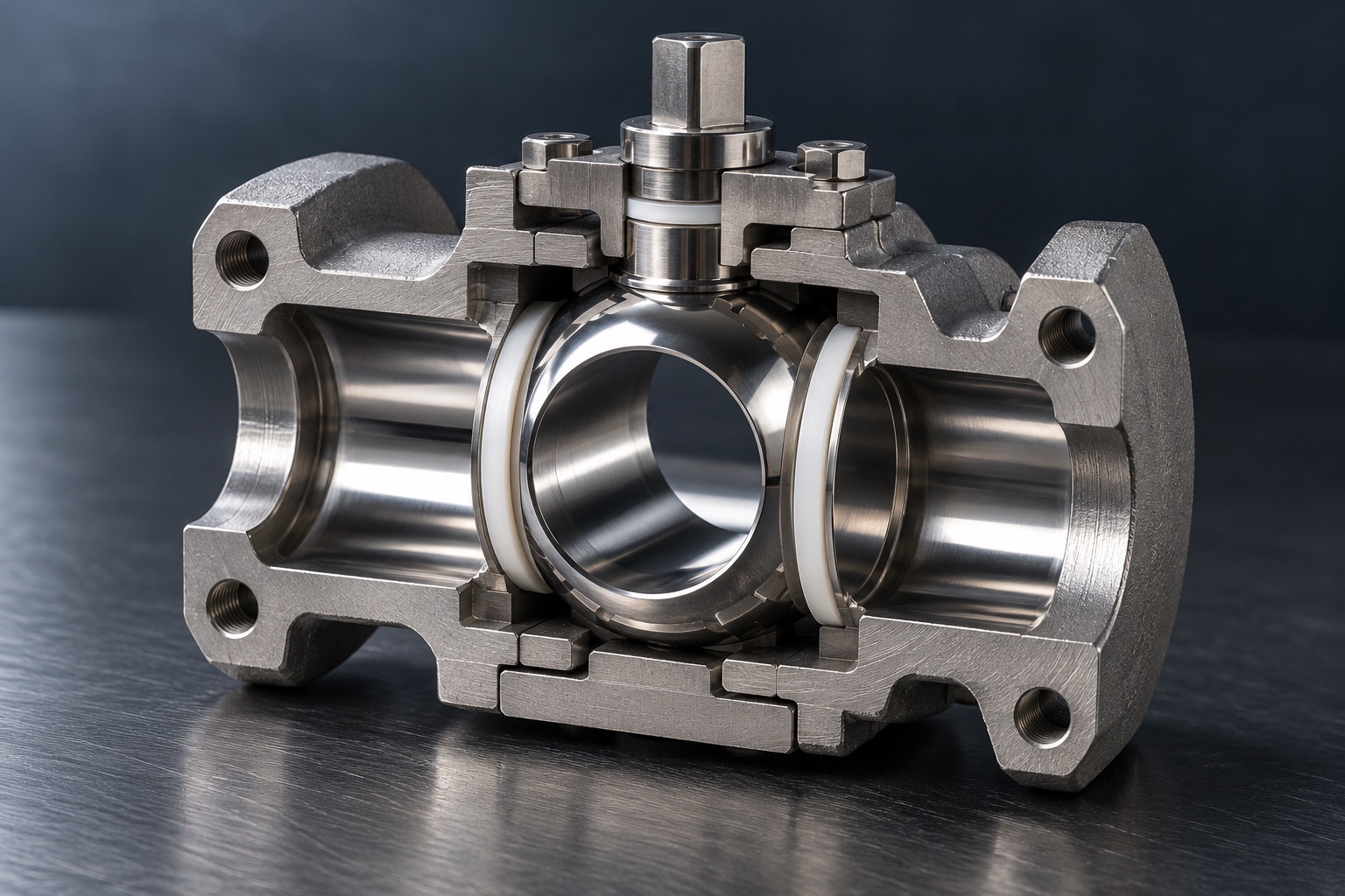
- Whether the wetted path is free of crevices at every joint, including under seats and behind seals
- Whether the component drains, and in which orientation it has to be installed to do so
- Whether it can be opened for inspection without cutting the line, which decides two-piece against three-piece construction with a clamp or welded end
- Seat and seal material against the coolant, its glycol content and its inhibitor package, at loop temperature
- Base material with its cast or wrought grade named, since the alloy decides what the corrosion product is
- Whether the supplier can state the finish they actually achieve, rather than the finish they can quote
What this does not settle
The transfer is a transfer of principles, not of certification. A component built to sanitary geometry is not thereby qualified for a cooling loop, and nothing in ASME BPE or 3-A was written with heat transfer in mind.
Connection type is a separate question. Whether a given loop uses clamp joints, welded joints or quick disconnects is decided by serviceability, rack layout and the loop architecture, and this article makes no claim about which is prevalent in current CDU designs.
The cleanliness figures quoted here are datacom guidance for the technology cooling system rather than a specification any particular operator has adopted. Individual programmes set their own, and several set tighter ones.
Frequently Asked Questions
Related Articles
- Ball Valves for Data Center Liquid Cooling
- Direct-to-Chip vs Rear-Door Valve Requirements
- Why Liquid Cooling Turns Manual Ball Valves Into Actuated Ones
- Is CF8M the Same as 316? What Changes When a Body Is Cast
- Ball Valve Seat Material Guide: PTFE vs RPTFE vs PEEK vs Metal
- Why Data Centers Choose Three-Piece Ball Valves
- Three-Piece Sanitary Ball Valve, Clamp or Butt Weld Ends
- What Surface Finish Does a Sanitary Valve Need?
- Stainless Steel Ball Valve OEM Manufacturing in Taiwan
Referenced standards and guidance: ASHRAE datacom series (facility water system and technology cooling system water quality guidance), ASME BPE (bioprocessing equipment, surface finish designations and joint geometry), 3-A Sanitary Standards (hygienic equipment design for dairy, food and beverage).
Microchannel geometry and filtration figures are typical published values for cold plate designs and vary between products. Water quality figures are guidance for the technology cooling system and are not a specification adopted by any particular operator. Surface finish designations are quoted as maxima; a supplier's achieved finish is a separate question from the designation they can quote.