Why a Tighter-Sealing Ball Valve Takes More Torque to Turn
Key Takeaway
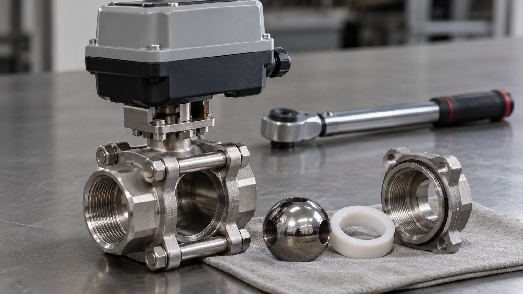
A seat that seals by pressing against the ball also resists the ball turning. Habonim, a ball valve maker, writes that friction between ball and seat is “responsible for most of the valve torque” and that the initial ball/seat torque depends on the seat preload the designer sets and on the seat material. The stem packing adds to it: if the stem nut is too tight the torque rises, and if it is too loose the stem is more likely to leak. Both makers size actuators from the breakaway torque with a multiplier, and the multipliers differ: Habonim adds 20% as standard and replaces it with 0.8 to 2.0 depending on service, while Islip Flow Controls multiplies by a fluid factor and a service factor. Neither document measures how much sealing is gained per unit of torque, so a valve maker’s published torque curve for the exact valve is the number to ask for.
Where does the torque of a ball valve come from?
Mostly from the seat pressing on the ball, plus the stem packing. Habonim’s valve torque data sheet says the torque needed to operate a ball valve “is a function of friction between the valve’s metal parts and its soft sealing materials”, and that the friction points in a floating ball valve are the stem and the ball and seat. It lists the factors that influence operating torque in three groups.
| Group | Factors named by Habonim | What the other maker adds |
|---|---|---|
| Design | Initial preload set by the designer, production tolerance, flexibility of the seat design, contact surface between ball and seat | Seat compression forces make the seat flow into minute surface imperfections of the ball |
| Material | Coefficient of friction of the seat | RTFE gives lower torque than the harder, higher-friction Delrin or PEEK |
| Application | System pressure, media (dry, lubricant, abrasive), temperature, frequency of operation | Viscous fluids raise torque, oils lower it, dry gas raises it, and low-frequency operation lets the seat flow into the ball surface |
The two documents agree on the main point. Habonim writes that the ball and seat friction “is responsible for most of the valve torque”, and that the valve’s initial ball/seat torque “is a function of the seat preload (determined by the designer) and the seat material”. In a floating ball design the system pressure forces the ball into the downstream seat, which in Habonim’s words makes the torque “very sensitive to service conditions in general and to the system pressure in particular”.
Does more seat compression cost more torque?
The documents describe the cost side clearly and do not measure the benefit side. Preload and seat compression are named as torque factors, and they are also what presses the seat against the ball. Neither document gives a figure for how much sealing is gained for each unit of added torque, so the claim that a valve can have both a very high seat compression and a low torque has to be shown by the valve maker with data, not assumed.
The stem side has a documented trade-off. Habonim says that when the stem nut is tightened to compress the stem sealing, friction in the stem assembly rises. If the nut is too loose, “the probability of stem leakage is increased”. If it is too tight, the stem torque is higher and “will increase the general torque of the valve”, which might result in faulty actuator sizing. Habonim therefore tells users to follow the stem adjustment instructions in each product manual.
Islip Flow Controls notes that the effect of the stem seal depends on the packing chamber depth and the type of packing, and that it is more dominant in smaller valves, where its share of the total torque is larger. It also states that for small valves the effect of differential pressure is minimal compared with the assembly stress on the seats and stem seal, so the torque stays basically constant over the operating differential pressure of the valve body. Both statements are from valve makers describing their own product ranges and should be read as such.
What do breakaway, running and ending torque mean?
They are three points on the stroke, and breakaway is the largest. Islip Flow Controls says the published valve torques are breakaway torques from the closed position, and that they are the highest torques expected, not counting dynamic forces from flow through the valve. As the ball turns, the torque decreases and is then called run torque. At the end of the stroke, as ball and seats return to full contact, the torque rises again, “but to an amount less then the valve breakaway torque”, and this is the valve ending torque.
For a spring-return or scotch-yoke actuator, Islip Flow Controls recommends factoring the breakaway torque by 0.7 for the running torque and 0.8 for the ending torque. Habonim writes that its pressure-torque curves show the breakout torque (BTO) with the ball in the closed position. Habonim also gives T2, the valve torque at zero differential pressure from the same curve, as the second check for spring actuators.
How do two valve makers size an actuator from it?
Each starts from breakaway torque and then multiplies, and the multipliers are not the same. The table sets the two methods side by side.
| Item | Habonim | Islip Flow Controls |
|---|---|---|
| Starting value | Breakout torque (BTO) from the curve for valve size, seat material and differential pressure | Basic valve torque from the chart for size and maximum differential pressure |
| Standard margin | Add 20% for pneumatic actuators in standard services | Multiply by fluid factor F1 and service factor F2 |
| Special service | Correction factor replaces the 20%: 1.8 for emergency shut-down and for IEC 61508 SIL installations, 1.5 for cryogenic below −60°C, for valves operated less than once a day and for control valves | Example: a valve operating less than once a day on clean, non-lubricating service uses F1 = 1.0 and F2 = 1.5 |
| Media | 1.5 for dirty gas such as natural gas and for chlorine, 1.3 for dry gas, 2.0 for viscous slurry above 100 cP, 0.8 for oil, thermal oil and lubricant | Fluid factor F1; its values are not printed in the pages read |
| Extra margin | None on top of the correction factor | A further 1.5 is suggested for pneumatic actuators to cover reduced air supply pressure |
| Test basis of the data | Theoretical calculation and laboratory tests with water and nitrogen at ambient temperature; the curves are averages of several measurements | Not stated in the pages read |
Islip Flow Controls’ worked example takes a 2-inch Series 2FB10 at 500 psig differential pressure, with a basic valve torque of 350 in.-lb (about 39.5 N·m). With F1 of 1.0 and F2 of 1.5 the minimum recommended actuator torque is 350 × 1.0 × 1.5 = 525 in.-lb, about 59.3 N·m. The company says that with both factors applied, additional safety factors are usually not required for constant-torque actuators, which it names as double-acting pneumatic and electric. It also says that this procedure is a guide only and that it takes no responsibility for actuator selection.
Which common shortcuts are wrong?
Adding a generic margin on top of the maker’s factor, and treating a catalogue number as a guarantee. Habonim states that its correction factors are to be used “instead of the standard safety factor and not on top of it”. Stacking a 1.5 service factor, a 20% margin and a further 1.5 would multiply to 1.5 × 1.2 × 1.5 = 2.7 times the starting torque. That matters because Habonim warns that the maximum torque on its graphs matches the material and series limit and should not be extrapolated to higher figures. Check the stem and series limit with the valve maker before choosing an actuator with a large output.
The second shortcut is to size on running torque. Islip Flow Controls says that breakaway torque is the highest expected, so a motor sized to the running value has less than the valve may need after a period closed. Why Are Data Center Cooling Valves Electric Rather Than Pneumatic? covers that case for cooling loops.
What should be asked for on a valve and actuator order?
- The breakaway torque for the exact valve size, seat material and differential pressure, from the valve maker, with the test conditions behind it.
- The valve maker’s own factors for the service, and a statement of whether they replace or add to a standard margin.
- The torque at zero differential pressure, and the running and ending torque, if a spring-return actuator is used.
- The stem and series torque limit, so the actuator output stays under it.
- The stem nut adjustment instruction, and who sets it before delivery.
- Whether the valve will sit closed for long periods, and a test of breakaway torque after such a period for the real valve and actuator together.
The seat polymers are compared in Ball Valve Seat Material Guide, the difference between floating and trunnion designs in Floating vs Trunnion Ball Valve, and leakage acceptance in API 598 vs ISO 5208.
What do these documents not settle?
Both sources are valve makers’ technical pages, not an independent standard or test report. Habonim’s sheet was read by text recognition from a PDF, so numbers should be checked against the original. The documents do not quantify how much leak-tightness a given amount of seat preload buys, do not give a torque value for any specific low-torque design, and describe different valve ranges, so their factors cannot be swapped. Temperature effects are named by Habonim as a factor but are not quantified in the pages read.
Frequently Asked Questions
Why does a ball valve with a tighter seat seal need more torque?
The seat seals by pressing on the ball, and the same contact resists rotation. Habonim states that ball/seat friction is responsible for most of the valve torque and that the initial value is a function of the seat preload set by the designer and the seat material.
What is breakaway torque?
The torque needed to start the ball turning from the closed position. Islip Flow Controls describes it as the highest torque expected, apart from dynamic forces caused by flow through the valve, and says it comes from the seat material flowing into minute surface imperfections of the ball under seat compression.
Does the stem packing affect torque?
Yes. Habonim says tightening the stem nut raises the friction in the stem assembly. Too loose raises the chance of stem leakage, too tight raises the stem torque and can lead to a wrongly sized actuator. Islip Flow Controls adds that the packing matters more in smaller valves, where it is a larger share of the total.
Does a valve that is rarely operated need a larger actuator?
Both makers say frequency of operation changes torque. Habonim lists a correction factor of 1.5 for valves operated less than once a day, and Islip Flow Controls lists a service factor of 1.5 in its worked example for a valve operating less than once a day.
Do dry gas and oil change the torque?
Yes. Islip Flow Controls says lubricating services such as oils tend to reduce torque and dry services such as gas result in higher torque. Habonim lists 1.3 for dry gas and 0.8 for oil, thermal oil and lubricant.
Is there one standard safety factor for sizing a ball valve actuator?
Not in the two documents read. Habonim adds 20% to its curve values for pneumatic actuators in standard services and replaces that with a correction factor for special applications. Islip Flow Controls multiplies the basic torque by a fluid factor and a service factor and suggests a further 1.5 for pneumatic actuators. Use the valve maker’s own method.
Related Articles
- Why Are Data Center Cooling Valves Electric Rather Than Pneumatic?
- Why Is Liquid Cooling Turning Manual Ball Valves Into Actuated Ones?
- Manual, Pneumatic, or Electric? How to Match Your Actuator to Your Process
- Floating vs Trunnion Ball Valve: Design, Torque and Selection
- Ball Valve Seat Material Guide: PTFE vs RPTFE vs PEEK vs Metal
- API 598 vs ISO 5208: Valve Leakage Rates Compared
- Stainless Steel Ball Valve OEM Manufacturer in Taiwan
- Your Drawing Says Belimo. Is That Enough to Order Actuated Ball Valves for Data Center Cooling?
Referenced sources: Habonim, Data Sheet – Valve Torques, Islip Flow Controls, Technical Information: Valve Torque and Sizing of Actuators.
Quotations are from the two PDFs read from their text layers or by text recognition, so check figures against the originals. Conversion to N·m uses 1 in.-lb = 0.113 N·m. The factors above describe those makers’ products and are not a standard. The cover image is a generated illustration, not a photograph of a particular product.