How Do You Specify a Tri-Clamp Sanitary 3-Piece Ball Valve So It Actually Fits?
Key Takeaway
A Tri-Clamp joint closes when the two flange outside diameters (D2) match, because the clamp and gasket only see the flange. Everything behind the flange, meaning the tube it welds to, its bore and its length, comes from a different standard (ASME BPE, ISO 1127, DIN 32676 or BS 4825). That is why “1/2 inch Tri-Clamp” is not a complete specification: depending on the tube standard, a nominal 1/2 inch ferrule has a flange of about 25, 34 or 50.5 mm, and those do not mate. Two ferrules that do mate can still leave a step in the bore, up to 3.8 mm per side between a 1 inch ASME tube and an ISO 1127 DN25 tube. Specify a sanitary three-piece ball valve by tube standard, flange D2 in millimetres, ferrule length, bore against tube ID, seat type, gasket material, clamp type and cleaning method. A three-piece body makes the valve cleanable out of the line. It does not remove the cavity around the ball.
What does “Tri-Clamp” actually standardise?
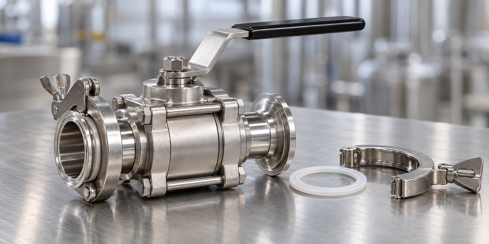
A Tri-Clamp joint is three parts: two identical flanged ferrules, a gasket between them and a hinged clamp around the back of both flanges. There is no male and female half, and no tool is needed to open it. The clamp and the gasket are cut to the flange. They know nothing about the tube.
So the number that decides whether two ferrules fit is the flange diameter, D2 in the dimension tables. The same few values recur across every tube standard, because each one is a clamp size:
| Flange D2 | ASME BPE tube | BS 4825-3 tube | DIN 32676 | ISO 1127 tube | Schedule 5 pipe |
|---|---|---|---|---|---|
| about 25 mm | 1/4" to 3/4" | 1/2", 3/4" | – | DN8, DN10 | – |
| 34 mm | – | – | DN10 to DN20 | DN15 (also made with 50.5) | – |
| 50.5 mm | 1", 1 1/2" | 1", 1 1/2" | DN25 to DN40 | DN15 to DN32 | 1/2" to 1 1/4" |
| 64 mm | 2" | 2" | DN50 | DN40 | 1 1/2" |
| 77.5 mm | 2 1/2" | 2 1/2" | – | DN50 | 2" |
| 91 mm | 3" | 3" | – | DN65 | 2 1/2" |
| 106 mm | – | 3 1/2" | – | DN80 | 3" |
| 119 mm | 4" | 4" | – | – | 3 1/2" |
The smallest flange is 0.984 in, which is 25.0 mm, in the ASME BPE tables of a manufacturer that prints inch values. Some tables round it to 25.4 mm. Treat the two as one clamp size and ask the maker which they mean.
Read across the 50.5 mm row. One clamp, one gasket size, and at least five different tubes behind it. DIN 32676 sorts them into three series: A for metric tube to DIN 11850, B for ISO 1127 tube and C for imperial tube to ASME BPE, in the wording of the distributors that sell them. The ISO standard for these couplings, ISO 2852:1993, has been withdrawn since 31 July 2018, and still gets quoted. Its table of flange diameters (50.5, 64, 77.5, 91, 106, 119, 130 mm and up) is the same series the DIN and ASME catalogues print.
Every table checked prints the same flange numbers, and a distributor states that the flange sizes are common to all three standards. None of the standard texts available for this article says outright that equal flanges from different standards mate, and ISO 2852 itself does not standardise the clamp. For a critical joint, have the clamp and gasket maker confirm the pairing.
Why is “1/2 inch Tri-Clamp” not a specification?
Because the small sizes split three ways. The same nominal size, taken from different tube standards, lands on a different flange:
3/4 inch behaves the same way. An ASME BPE or BS 4825-3 3/4 inch ferrule has the small flange, an ISO 2037 or Schedule 5 3/4 inch ferrule has 50.5 mm, and DIN 32676 DN20 has 34 mm. A purchase order that says “3/4" Tri-Clamp” has not said which of the three.
The word that is safe to put on a drawing is the flange D2, in millimetres, next to the tube standard. Clamp catalogues already work this way: one maker’s smallest clamp is listed for 1/2 to 3/4 inch and for DN6 to DN10 together, and its next two sizes are 34.0 and 50.5 mm.
What happens when two standards meet at one clamp?
The clamp closes, the gasket seats, and the bore does not line up. Take a 1 inch ferrule from five tables, all with a 50.5 mm flange:
| Ferrule | Tube OD (mm) | Bore D1 (mm) | Length L (mm) |
|---|---|---|---|
| ASME BPE 1" | 25.4 | 22.1 | 28.6 short, 44.5 long |
| BS 4825-3 1" | 25.65 | 22.2 | 21.5 |
| ISO 2852 Table 2, nominal 25 (ISO 2037 tube) | 25.6 | 22.6 | 21.5 |
| DIN 32676 DN25 (series A) | 29 | 26 | 21.5 |
| ISO 1127 DN25 | 33.7 | 29.7 | 21.5 |
The ASME bore is the tube OD less two walls of 1.65 mm. The others are as printed in the ISO 2852 table and in manufacturer catalogues.
Join an ASME BPE 1 inch ferrule to an ISO 1127 DN25 ferrule and the bores are 22.1 and 29.7 mm. That is a 7.6 mm difference in diameter, so a 3.8 mm ledge on each side of the flow path. The joint is leak-tight and the ledge is a place where product sits. EHEDG’s hygienic design criteria say that where seals or gaskets are used, their design must leave no crevice where soil residues can be trapped, and that pipework must be self-draining or drainable. A ledge at the joint is the geometry that test is written against. The surface finish article covers the finish side of the same joint.
For a valve, this lands on the end pieces. If a valve is supplied with 1 inch ASME ferrule ends and the line behind it is DIN DN25 tube, the valve is not wrong and the line is not wrong. The pair is.
Length matters too. In ISO 2852 the ferrule, which the standard calls a liner, is dimensioned by its total length, neck and flange together: 21.5 mm up to a 101.6 mm tube. The ASME BPE tables give an overall length as well, 28.6 mm for the short ferrule and 44.5 or 57.2 mm for the long. The two are defined the same way, so the difference is real: about 7 mm per end, 14 mm across a pair. For DIN DN10 to DN20, two catalogues disagree between 18 and 21.5 mm. Check the face-to-face dimension of the finished valve, ferrules included, against the gap in the skid drawing. The general method is in the face-to-face article.
What does a three-piece body solve, and what does it leave?
A ball valve has a pocket by construction. Alfa Laval’s sanitary ball valve leaflet opens the point in one line: all ball valves feature a cavity behind the ball. With the valve open, product sits in that space and the line cannot flush it out. A trade source on sanitary valves says ball valves are not typically considered sanitary valves for that reason, and that if one must be used it should be a three-piece design that can be removed and taken apart for cleaning out of place (COP). The same source says a conventional sanitary ball valve is not suited to clean-in-place (CIP).
The standards side is moving the same way. 3-A publishes a ball valve standard, 3-A 68-01, Ball-Type Valves for Milk and Milk Products, last revised in 2023. A trade-press article reports that its update treats ball valves as COP only, and that a ball valve not marked COP only can no longer carry the 3-A mark. That is a secondary report and the standard is sold, so no clause numbers are given here.
So the three-piece body does one specific thing. It turns the cavity from a place you cannot reach into a place you reach by disassembly. With a Tri-Clamp end on each side, the valve comes out of the line without tools, and the centre section gives access to the ball and seats.
| Design feature | What it solves | What it leaves open |
|---|---|---|
| Three-piece body, Tri-Clamp ends | Valve leaves the line without tools; ball and seats can be reached and cleaned or replaced | Cleaning is by removal. The cavity is still there between cleanings |
| Cavity-filled seats | Shrinks the pocket around the ball so product has fewer places to settle between operation and cleaning | Alfa Laval lists the cavity filler (encapsulating seats) as an option and says it cannot be combined with its cavity-clean option. The choice is a smaller pocket or a cleaning route into the pocket |
| Bore equal to tube ID | No step between the valve bore and the tube it joins | Larger ball and body for the same line size |
| Reduced port | Smaller, lighter body | The bore is smaller than the ferrule it joins, so a step exists at each end by construction. Whether that is acceptable is for the process specification to say |
EHEDG Guideline 14, Requirements for valves in hygienic and aseptic processes, third edition, August 2020, is the valve guideline. It covers all valves in contact with food processed hygienically or aseptically, with general requirements on materials, drainability and microbial impermeability. It is sold for EUR 100 and EHEDG has said a revision is planned. The catalogue page does not say whether it addresses ball valves as a type, so this article does not quote it.
What do the clamp and the gasket decide?
Four things the valve body does not.
Temperature. The gasket is usually the limit on a Tri-Clamp joint. One manufacturer’s gasket table lists these ranges:
| Gasket material | Temperature range |
|---|---|
| EPDM | −46 to 132 °C (shortly up to 150 °C) |
| Fluoroelastomer (FPM) | −29 to 204 °C |
| Silicone (MVQ) | −62 to 232 °C |
| PTFE | −78 to 232 °C |
The same catalogue gives a sterilisation temperature of 150 °C for its stainless clamps and lists EPDM only to 132 °C continuous. A cycle hotter than 132 °C is outside the continuous range that table gives EPDM. Check the gasket against the cycle, not against the valve.
Pressure. The pressure the joint holds is set by the clamp type, the clamp size and the gasket, and it is a different number from the valve body rating. The clamp catalogue states that maximum operating pressure depends on the assigned elastomer, and describes its double-bolted type as suited to 10 to 30 bar depending on clamp size. A body rated to 1000 psi WOG, about 69 bar, can sit in a joint that holds a fraction of that. If the line pressure is anywhere near the clamp rating, put the clamp type on the order.
Clamp type. The same catalogue lists a wing-nut clamp with a torque rating of 5 Nm and a hexagon-nut clamp rated at 20 Nm. The wing nut is what lets a joint be opened by hand. The hexagon nut is what holds a higher pressure class. Which one is on the order decides how the joint is tightened and by whom.
Compliance of the elastomer. The catalogue lists conformance certificates to 21 CFR 177.2600 for its elastomer gaskets and 21 CFR 177.1550 for PTFE. Those are the US food contact rules for rubber articles intended for repeated use and for perfluorocarbon resins. A gasket is a separate part with its own paperwork, and the valve’s certificate does not cover it.
What should a Tri-Clamp valve order contain?
- Tube standard and size, for example ASME BPE 1 inch or ISO 1127 DN25. Not “1 inch Tri-Clamp” alone.
- Flange D2 in millimetres. It is the one number the clamp depends on.
- Ferrule length, and the overall length of the finished valve with ferrules fitted.
- Bore against the tube ID. State the step you can accept, if any. This is also where a reduced port gets decided.
- Seat type. Standard or cavity-filled, and the seat material.
- Cleaning method. COP by removal, or CIP, and whether the process includes steam. The answer changes which seat is sensible.
- Gasket material and the highest cycle temperature, with the clamp type and the line pressure.
- Surface finish as a named designation, for the bore, ball and ferrule faces. See the surface finish article for how to write it.
- Material documents for the body, ball and ferrules, by heat.
What does this not settle?
Whether a valve is 3-A, ASME BPE or EHEDG compliant is a question about the whole component, its design and its documentation. It is not answered by the ferrule size, and quoting a standard’s name on a drawing does not make a part compliant. The sanitary piping rules article sets out how 3-A and ASME BPE differ.
Mounting orientation for drainage, the exact face-to-face of each standard’s valve, and the steam and CIP limits of a given seat are properties of a specific model. They have to come from that model’s data, not from a category description.
Frequently Asked Questions
Are ISO and ASME Tri-Clamp ferrules interchangeable?
The flanges are, when their outside diameters match, because the clamp and gasket only see the flange. A 50.5 mm flange from an ASME BPE 1 inch ferrule closes against a 50.5 mm flange from a DIN 32676 DN25 ferrule. The tubes behind them are not interchangeable, and the bores differ: 22.1 mm on the ASME 1 inch ferrule against 29.7 mm on ISO 1127 DN25, which leaves a step in the flow path.
What is a 1.5 inch Tri-Clamp?
It is a clamp size for a 50.5 mm flange. The same flange appears on ASME BPE 1 and 1 1/2 inch tube, DIN 32676 DN25 to DN40, ISO 1127 DN15 to DN32 and Schedule 5 pipe from 1/2 to 1 1/4 inch. The label names the clamp. It does not name the tube.
Can a three-piece sanitary ball valve be cleaned in place?
A trade source on sanitary valves says a conventional ball valve is not suited to clean-in-place and recommends a three-piece design that can be removed and disassembled for cleaning out of place. Whether a particular model with cavity-filled seats suits CIP is a question for that model's data.
Which gasket material suits a Tri-Clamp valve joint?
It depends on the highest cycle temperature. One manufacturer lists EPDM at -46 to 132 C, fluoroelastomer at -29 to 204 C, silicone at -62 to 232 C and PTFE at -78 to 232 C. Choose from the cycle temperature and the cleaning chemicals, and ask for the gasket's own food contact documentation.
Does a Tri-Clamp valve hold the pressure on its body rating?
Not necessarily. The joint is limited by the clamp type, the clamp size and the gasket. One clamp maker describes its double-bolted type as suited to 10 to 30 bar depending on size, while a valve body can be rated to 1000 psi WOG, about 69 bar. Put the clamp type on the order when line pressure is near the clamp rating.
Is ISO 2852 still the current standard for Tri-Clamp ferrules?
ISO 2852:1993, Stainless steel clamp pipe couplings for the food industry, has been withdrawn since 31 July 2018, according to Wikipedia, although it is still widely cited. DIN 32676 is listed by DIN Media in its 2025-09 edition, with series A for metric DIN 11850 tube, B for ISO 1127 tube and C for imperial tube to ASME BPE. Both print the same flange diameter series.
Related Articles
Sources: ISO 2852:1993 full-text sample (flange series, liner length) and its withdrawal status; DIN 32676 listing (title and current edition); ASME BPE ferrule dimensions as printed in Dockweiler’s ASME BPE components catalogue; Armat and Flowsource DIN 32676 ferrule tables; HD Process and sanitaryfittings-cad compilations (used as cross-checks); flange sizes common across standards; clamp sizes, torque ratings, pressure statements and gasket temperature table from the Connectors Verbindungstechnik Tri-Clamp catalogue (printed 2006); Alfa Laval sanitary ball valve leaflet; Crane Engineering on valves in sanitary CIP/COP service; 3-A Sanitary Standards listing and a Pumps & Systems article on the ball valve update; EHEDG Doc. 8, Hygienic Equipment Design Criteria (2nd edition, 2004) and EHEDG Guideline 14.
ISO 2852, DIN 32676, BS 4825-3, ASME BPE, 3-A 68-01 and EHEDG Guideline 14 are sold and were not read in full, apart from the ISO 2852 sample. ASME BPE figures come from a manufacturer catalogue that prints the table with its 2009 numbering; BPE-2026 was published in June 2026 and its table numbering was not checked. ASME bores are calculated from the tube OD and a 1.65 mm wall. Verify dimensions against the current standard before a drawing is released. Clamp pressure and torque figures are one maker’s catalogue values and vary by clamp type. No cleaning cycle count, drainage angle or leakage rate is given, because each depends on the specific valve model and the process.