What Are the Face-to-Face Dimensions of a Ball Valve?
Key Takeaway
Half of this question has a standard answer and half of it does not. ASME B16.10 fixes face-to-face dimensions for flanged valves and end-to-end for butt welding and grooved ends, so a Class 150 flanged ball valve is 108 mm at 1/2 inch and 229 mm at 4 inch regardless of who made it. Threaded and socket weld ends are outside the scope of that standard. Nothing sets the length of a threaded ball valve, which means two suppliers can both be entirely correct and ship valves that are not the same length. For a flanged valve the dimension comes from the standard. For a threaded valve it comes from the supplier's drawing, and a drawing is the only place it exists.
What the standard actually covers
ASME B16.10 is the dimensional standard for valves, and its scope is narrower than the way it gets cited. It covers gate, globe, plug, ball, check and butterfly valves, and it covers them by end connection rather than by type.
| End connection | In ASME B16.10 | What the dimension is called |
|---|---|---|
| Flanged | Yes | Face to face, measured between the gasket contact surfaces |
| Butt welding | Yes | End to end |
| Grooved | Yes | End to end |
| Wafer, between flanges | Yes | Covered as a valve type intended for assembly between flanges |
| Threaded | No | Not standardised |
| Socket weld | No | Not standardised |
The last two rows are the ones that matter to anyone specifying small bore valves, because threaded ends are where most 1/4 inch to 3 inch ball valves live. A drawing that says dimensions per ASME B16.10 next to a threaded valve is citing a standard that does not reach it.
Class 150 flanged ball valves
Face to face is measured between the gasket contact surfaces, which are the raised faces on a raised face flange. These are the Class 150 figures.
| NPS | DN | Face to face, mm | Approx. inches |
|---|---|---|---|
| 1/2" | DN15 | 108 | 4.3 |
| 3/4" | DN20 | 117 | 4.6 |
| 1" | DN25 | 127 | 5.0 |
| 1-1/4" | DN32 | 140 | 5.5 |
| 1-1/2" | DN40 | 165 | 6.5 |
| 2" | DN50 | 178 | 7.0 |
| 2-1/2" | DN65 | 190.5 | 7.5 |
| 3" | DN80 | 203 | 8.0 |
| 4" | DN100 | 229 | 9.0 |
The standard also distinguishes a long pattern from a short pattern for ball valves. Through the Class 150 range above the two are the same, and they separate at higher classes and larger sizes. Where a specification names one, it is naming a spool length as much as a valve, and a short pattern valve dropped into a gap built for a long pattern leaves a gap that has to be made up.
Why the threaded gap exists
A flanged joint has a natural datum. The gasket surfaces are flat, they are square to the axis, and the flange faces of the mating pipework sit in a known place, so a standard can fix a number between them and every valve that meets it will drop into the same spool.
A threaded joint has no equivalent. Where a pipe ends inside a tapered thread depends on how far it was made up, and how far it was made up depends on the thread tolerance, the sealant and the installer. There is no plane in the assembly that a standard could sensibly measure to.
So the dimension that does exist for a threaded valve, the overall end to end length, is a property of the valve rather than of the joint. Manufacturers publish it because customers need it for layout, and each one arrives at a different figure.
What makes one threaded valve longer than another
Four things move the length, and all four are design choices rather than tolerances.
| Design choice | Effect on length |
|---|---|
| Two-piece against three-piece body | A three-piece body has two end caps and a centre section, with joint faces and bolting that a two-piece does not carry |
| Full port against reduced port | A full port valve houses a larger ball and a larger seat pocket, which the body has to be long enough to contain |
| Thread depth at each end | The tapped length has to accept full thread engagement, and how much is provided is a design decision |
| Wall thickness for the pressure rating | A higher rated body is thicker, and the material has to go somewhere |
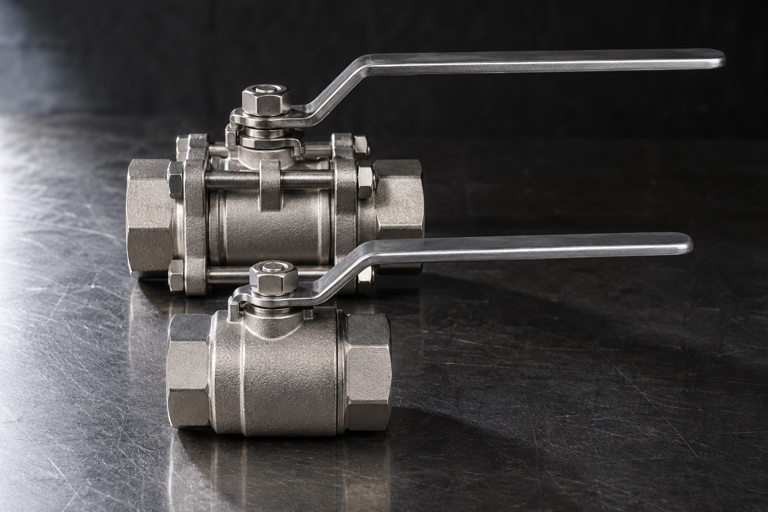
None of those is an error. Two valves of the same size and rating, one full port three-piece and one reduced port two-piece, are different lengths because they are different valves. The problem arrives when a drawing treats them as interchangeable because the standard does not say they are not.
The substitution that catches people
A threaded ball valve fails in service and a replacement is ordered by size and rating. The replacement arrives correct on both counts and does not fit the gap.
Nothing went wrong with the order. The original was a reduced port two-piece and the replacement is a full port three-piece, or the two came from different manufacturers, and no standard was ever holding them to the same length. The size on the box describes the bore, not the envelope.
The practice that avoids it is to record the end to end length of the valve actually installed, alongside the size and rating, in whatever the maintenance record is. That figure exists on the supplier's drawing and nowhere else, so it has to be captured while the drawing is still to hand.
The two dimensions that get left off
Length decides whether a valve fits the pipe run. Two other figures decide whether it can be operated once it is in, and a catalogue page that lists only face to face leaves both of them out.
Height to the top of the handle. Measured from the centreline of the bore, this is what has to clear whatever sits above the line. A valve under a duct, inside a cabinet or against a ceiling can be the right length and still not go in.
Handle swing radius. A lever needs a quarter circle of clear space to travel through. The radius is the length of the lever, and the arc it sweeps has to be empty for ninety degrees, not just at the two end positions. A neighbouring pipe halfway through the arc stops the valve at forty-five degrees, which is a throttled valve rather than an open one.
Both figures are on the supplier's drawing for the same reason the length is: no standard sets them.
Socket weld has the same gap
Socket weld ends sit outside ASME B16.10 alongside threaded ends, and for a related reason. A socket joint locates the pipe against a shoulder inside the fitting, then the pipe is pulled back before welding to leave a gap for expansion. Where the pipe ends is therefore set by the assembly practice rather than by the valve.
The consequence is the same as for threaded. A socket weld valve has an end to end length, it comes from the manufacturer, and two of them at the same size and rating are not required to match.
Measuring a valve before ordering its replacement
Where a threaded valve is being replaced and the original drawing is gone, the dimension has to come off the installed valve. Four measurements are enough to ask a supplier whether anything in range will fit.
- End to end, across the outside of both ends, with the valve still in the line. This is the figure the replacement has to match.
- Across flats on the hex at each end, which confirms the size and gives the supplier something to check the thread against.
- Centreline to the top of the handle with the valve open.
- Lever length, and whether the arc it sweeps is clear.
The first of those is the one that gets skipped, because size and rating feel like enough information. On a threaded valve they are not.
What to put on an enquiry
For a flanged valve the standard carries most of this. For a threaded valve none of it is implied.
- Size and pressure rating, which between them fix nothing about length on a threaded valve.
- End to end length, requested as a figure from the drawing rather than assumed from a catalogue range.
- Body construction, since two-piece and three-piece are different lengths at the same size.
- Port, since full port and reduced port are different lengths at the same size.
- Height to the top of the handle in the open position, which decides clearance above the line and is easy to forget on a valve that is being replaced in situ.
- Handle swing radius, since a lever needs a quarter circle of clear space and a wall or a neighbouring pipe removes it.
- Where the valve is being fitted into existing pipework, the length being replaced, so the supplier can say whether anything in range matches it.
What this does not settle
The figures above are Class 150 for flanged ball valves. Higher classes carry their own tables, and the long and short patterns separate as class and size increase, so a Class 300 valve is not a Class 150 valve with a different flange.
Face to face is a dimension between gasket surfaces and says nothing about flange outside diameter, bolt circle or bolt hole count, which come from the flange standard rather than from B16.10.
Nothing here gives the length of any particular threaded valve. There is no standard figure to give, which is the point of the article, and the number for a specific product comes from that product's drawing.
Frequently Asked Questions
Related Articles
- Flanged vs Threaded Ball Valve: Connection Type Selection
- Full Port vs Reduced Port Ball Valve
- 2-Piece vs 3-Piece Ball Valve: Design Differences
- Ball Valve Pressure Ratings: ASME Class 150 to 600
- What Do the Markings on a Ball Valve Body Mean?
- ISO 5211 Actuator Flange Dimensions: F03 to F100
- Stainless Steel Ball Valve OEM Manufacturing in Taiwan
Referenced standards: ASME B16.10, face-to-face and end-to-end dimensions of valves, for the scope and the Class 150 figures. ASME B16.5 governs the flanges themselves, including outside diameter, bolt circle and bolt holes, which B16.10 does not address. MSS SP-110 covers ball valves with threaded, socket welding, solder joint, grooved and flared ends, and addresses design and rating rather than length.
Class 150 face-to-face figures are quoted from published B16.10 reference tables and are given for orientation. A drawing for a specific product remains the governing document, and for a threaded valve it is the only document, since no dimensional standard applies to that end connection.